In this post, I’ll detail the configuration for Netscaler ADC Load Balancer when it’s deployed for the purposes of load balancing multiple ISE nodes
There’s already a great post by Brad Johnson available here: https://community.cisco.com/t5/security-knowledge-base/citrix-netscaler-cli-configuration-for-cisco-ise-radius-and/ta-p/4679861.
I will expand on that configuration and add screenshots on how things are configured through the GUI.
Topology
I’m going to cover the most basic topology. That is ISE nodes being behind the Load Balancer configured in Layer 3 mode. ISE nodes use the Load Balancer IP address as the default gateway.
Lab Testing
Netscaler provides a low bandwidth free version of ADC Load Balancer in AWS. I’ve created a terraform template to deploy ADC along with a set of FreeRADIUS servers to allow for learning and testing Netscaler configuration. The RADIUS servers are provisioned with username cisco and password cisco.
The template can be found here: https://github.com/vbobrov/terraform/tree/main/aws/freeradius-netscaler
The following topology is deployed:

ISE LB Best Practices
There are many detailed guides and forum discussions on this topic and I won’t cover all those details here. Be sure to review this document that goes into great details about LB and ISE requirements: https://community.cisco.com/t5/security-knowledge-base/how-to-cisco-amp-f5-deployment-guide-ise-load-balancing-using/ta-p/3631159
To summarize, these are the base requirements:
- ISE must see the original IP addresses of network devices
- To satisfy the previous requirement, LB must be deployed inline between network devices and ISE. In other words, return traffic from ISE to the network devices must flow through the LB.
- For RADIUS ports, persistence and LB should be done based on RADIUS Calling-Station-Id attribute rather than Source IP. Source IP should be the backup to Calling-Station-ID
- RADIUS Authentication (udp/1812) and RADIUS Accounting (udp/1813) for the same Calling-Station-Id should be forwarded to the same ISE node behind the LB.
- Service monitoring should be done using RADIUS polling, not ICMP or TCP. This will correctly detect when RADIUS server on ISE is ready
- CoA (udp/1700) traffic initiated from ISE towards network devices should be NAT’d to the IP address of the LB VIP
Netscaler Configuration
Source IP Mode
In order for ISE to properly handle RADIUS and TACACS requests from network devices
By default, ADC performs source NAT on the incoming requests. When these requests get to the nodes behind it, they’re NAT’d to the IP address of Load Balancer itself.
This can be enabled either globally or per-service. This link describes how to enabled this capability: https://docs.netscaler.com/en-us/citrix-adc/current-release/networking/ip-addressing/enabling-use-source-ip-mode.html
Globally, this can be enabled in the GUI or via CLI.


Per-service configuration will be covered later in this document.
CLI Configuration
enable ns mode USIPRadius Monitor
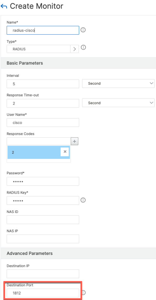
ADC natively supports RADIUS monitor that provides the ability to send synthetic RADIUS request to ISE nodes to check their status.
To add the monitor from the GUI navigate to Monitors and click Add

When filling out the form, be sure to specify 1812 as the destination port since we will apply the same monitor to RADIUS Accounting (1813) as well.
The configuration below looks for Access-Accept (Code 2). It is also possible to configured it to consider Access-Reject (Code 3) as well. Both codes can be specified at the same time.

CLI Configuration
add lb monitor radius-cisco RADIUS -respCode 2 -userName cisco -password <password> -radKey <secret> -LRTM DISABLED -destPort 1812
Add Servers
ADC refers individual hosts serving requests as Servers. Servers are added from a menu option of the same name


Using CLI
add server radius-1 10.1.1.13
add server radius-2 10.1.1.9
add server radius-3 10.1.1.119
add server radius-4 10.1.1.100
Add Service Groups
Service groups are added from the menu of the same name.

One service group is needed for each service: udp/1812, udp/1813 and tcp/49.

Once the service group is added, we add group members which are the servers defined in a previous step.


In order for ISE to see the original Network Device IP, we need to enable Use Client IP option


Next, we add a attach the Monitor to the group


Follow the same steps for udp/1813 and tcp/49. The following are screenshots for TACACS.


Use the same RADIUS monitor for TACACS as well

CLI Commands
add serviceGroup radius-auth RADIUS -maxClient 0 -maxReq 0 -cip DISABLED -usip YES -useproxyport NO -cltTimeout 120 -svrTimeout 120 -CKA NO -TCPB NO -CMP NO

add serviceGroup radius-acct RADIUS -maxClient 0 -maxReq 0 -cip DISABLED -usip YES -useproxyport NO -cltTimeout 120 -svrTimeout 120 -CKA NO -TCPB NO -CMP NO

add serviceGroup tacacs TCP -maxClient 0 -maxReq 0 -cip DISABLED -usip YES -useproxyport YES -cltTimeout 9000 -svrTimeout 9000 -CKA NO -TCPB NO -CMP NO

bind serviceGroup radius-auth radius-4 1812
bind serviceGroup radius-auth radius-3 1812
bind serviceGroup radius-auth radius-2 1812
bind serviceGroup radius-auth radius-1 1812
bind serviceGroup radius-auth -monitorName radius-cisco
bind serviceGroup radius-acct radius-4 1813
bind serviceGroup radius-acct radius-3 1813
bind serviceGroup radius-acct radius-2 1813
bind serviceGroup radius-acct radius-1 1813
bind serviceGroup radius-acct -monitorName radius-cisco
bind serviceGroup tacacs radius-4 49
bind serviceGroup tacacs radius-3 49
bind serviceGroup tacacs radius-2 49
bind serviceGroup tacacs radius-1 49
bind serviceGroup tacacs -monitorName radius-cisco
Perstence Groups
Persistence groups will configure the Load Balancer to send udp/1812 and udp/1813 traffic from the same Calling-Station-ID to the same ISE node.
For persistence, we use the following rule: CLIENT.UDP.RADIUS.ATTR_TYPE(31)

Virtual Servers
Next, we create Virtual Servers and attach them to Service Groups


For persistence, we use the same rule: CLIENT.UDP.RADIUS.ATTR_TYPE(31)

Repeat the same process for udp/1813 and tcp/49. The following are screenshots for TACACS.

For TACACS, persistence is based on source IP address

CLI Configuration
add lb vserver radius-auth RADIUS 10.2.1.1 1812 -rule "CLIENT.UDP.RADIUS.ATTR_TYPE(31)" -cltTimeout 120
add lb vserver radius-acct RADIUS 10.2.1.1 1813 -rule "CLIENT.UDP.RADIUS.ATTR_TYPE(31)" -cltTimeout 120
add lb vserver tacacs TCP 10.2.1.1 49 -persistenceType SOURCEIP -cltTimeout 9000

bind lb vserver radius-auth radius-auth
bind lb vserver radius-acct radius-acct
bind lb vserver tacacs tacacs
CoA NAT
Best practice for Load Balancers is to NAT CoA (udp/1700) traffic to the IP Address of the VIP.
We will create a rule to NAT udp/1700 traffic from specific ISE nodes only. It is also possible to create a rule for all udp/1700.
First step is to create a Data Set listing out ISE node IP addresses.


To perform NAT on ADC, we first need to define an ACL to match udp/1700 traffic. ACLs are created from System \ Network \ ACLs. We will create an extended ACL


When ACLs are created on ADC, they need to be applied to be activated.


Next, we add a NAT rule under System \ Network \ NATs \ RNAT


CLI Configuration
add policy dataset radius_servers ipv4
bind policy dataset radius_servers 10.1.1.13 -index 1
bind policy dataset radius_servers 10.1.1.9 -index 2
bind policy dataset radius_servers 10.1.1.119 -index 3
bind policy dataset radius_servers 10.1.1.100 -index 4

add ns acl CoA ALLOW -srcIP = radius_servers -srcPort = 1-65535 -destPort = 1700 -protocol UDP -priority 10
apply ns acls

add rnat coa-nat radius-coa
bind rnat coa-nat 10.2.1.1
Full CLI Configuration
# Add RADIUS Servers
add server radius-1 10.1.1.13
add server radius-2 10.1.1.9
add server radius-3 10.1.1.119
add server radius-4 10.1.1.100

# Add Service Groups
add serviceGroup radius-auth RADIUS -maxClient 0 -maxReq 0 -cip DISABLED -usip YES -useproxyport NO -cltTimeout 120 -svrTimeout 120 -CKA NO -TCPB NO -CMP NO
add serviceGroup radius-acct RADIUS -maxClient 0 -maxReq 0 -cip DISABLED -usip YES -useproxyport NO -cltTimeout 120 -svrTimeout 120 -CKA NO -TCPB NO -CMP NO
add serviceGroup tacacs TCP -maxClient 0 -maxReq 0 -cip DISABLED -usip YES -useproxyport YES -cltTimeout 9000 -svrTimeout 9000 -CKA NO -TCPB NO -CMP NO

# Add Vservers
add lb vserver radius-auth RADIUS 10.2.1.1 1812 -rule "CLIENT.UDP.RADIUS.ATTR_TYPE(31)" -cltTimeout 120
add lb vserver radius-acct RADIUS 10.2.1.1 1813 -rule "CLIENT.UDP.RADIUS.ATTR_TYPE(31)" -cltTimeout 120
add lb vserver tacacs TCP 10.2.1.1 49 -persistenceType SOURCEIP -cltTimeout 1800

# Add RADIUS Monitor
add lb monitor radius-cisco RADIUS -respCode 2 -userName cisco -password cisco -radKey cisco -LRTM DISABLED -destPort 1812

# Bind Vservers to Service Groups
bind lb vserver radius-auth radius-auth
bind lb vserver radius-acct radius-acct
bind lb vserver tacacs tacacs

# Add Persistency Group
add lb group radius -persistenceType RULE -persistenceBackup SOURCEIP -rule "CLIENT.UDP.RADIUS.ATTR_TYPE(31)"

# Bind Vservers to Persistency Group
bind lb group radius radius-auth
bind lb group radius radius-acct

# Bind RADIUS Servers to Service Groups
bind serviceGroup radius-auth radius-4 1812
bind serviceGroup radius-auth radius-3 1812
bind serviceGroup radius-auth radius-2 1812
bind serviceGroup radius-auth radius-1 1812
bind serviceGroup radius-acct radius-4 1813
bind serviceGroup radius-acct radius-3 1813
bind serviceGroup radius-acct radius-2 1813
bind serviceGroup radius-acct radius-1 1813
bind serviceGroup tacacs radius-4 49
bind serviceGroup tacacs radius-3 49
bind serviceGroup tacacs radius-2 49
bind serviceGroup tacacs radius-1 49

# Bind RADIUS Monitor to Service Groups
bind serviceGroup radius-auth -monitorName radius-cisco
bind serviceGroup radius-acct -monitorName radius-cisco
bind serviceGroup tacacs -monitorName radius-cisco

# Create dataset
add policy dataset radius_servers ipv4
bind policy dataset radius_servers 10.1.1.13 -index 1
bind policy dataset radius_servers 10.1.1.9 -index 2
bind policy dataset radius_servers 10.1.1.119 -index 3
bind policy dataset radius_servers 10.1.1.100 -index 4

# Create COA ACL
add ns acl radius-coa ALLOW -srcIP = radius_servers -srcPort = 1-65535 -destPort = 1700 -protocol UDP -priority 10 -kernelstate SFAPPLIED61
apply ns acls

# Create CoA NAT
add rnat coa-nat radius-coa
bind rnat coa-nat 10.2.1.1
Monitoring and Troubleshooting
Connection Table
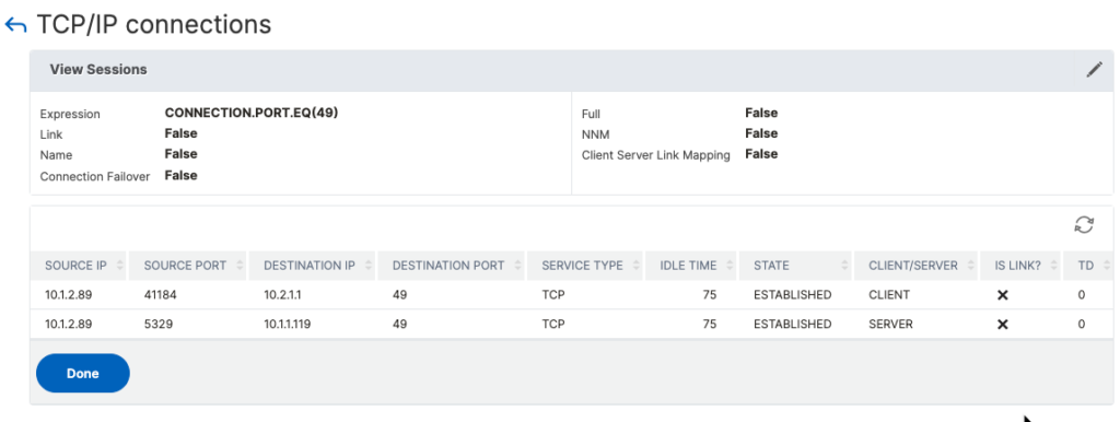
To view active connections, click on TCP/IP Connections in System \ Network.

It is possible to filter connections using Expression Builder


As I’m writing this, the connection table does not show Load Balanced UDP connections including RADIUS.
CLI Command
> show connectiontable CONNECTION.PORT.EQ(49)
SRCIP           SRCPORT DSTIP           DSTPORT SVCTYPE      IDLTIME STATE        Traffic Domain
10.1.2.89       41184   10.2.1.1        49      TCP          181     ESTABLISHED  0               C
10.1.2.89       5329    10.1.1.119      49      TCP          181     ESTABLISHED  0               S
Persistence Table
The table can be viewed from Traffic Management section.

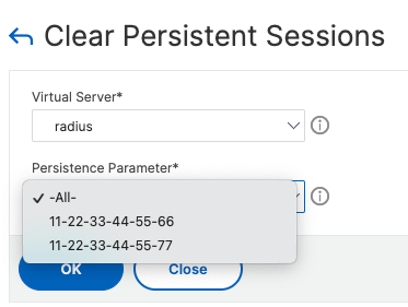
The following example shows two separate sessions based on the MAC address going to two different ISE nodes. Note that Virtual Server is set to the name of the Persistence Group and not individual services

To clear persistence records, click the Clear link shown on the screenshot above and select which records to clear.

CLI Command
> show persistentSessions radius
Type     SRC-IP   DST-IP  PORT  VSNAME      TIMEOUT  PERSISTENCE-PARAMETER
RULE   *        10.1.1.13  0     radius        54        11-22-33-44-55-66
RULE   *        10.1.1.9   0     radius        51        11-22-33-44-55-77

> show persistentSessions tacacs
Type       SRC-IP     DST-IP  PORT  VSNAME   TIMEOUT  PERSISTENCE-PARAMETER
SOURCEIP 10.1.2.89  10.1.1.9   49    tacacs     87        10.1.2.89

> clear persistentSessions radius
 Done
Packet Capture
Packet capture facility is available under System \ Diagnostics

Filter can be defined using Expression Editor

Once the capture is started, a confirmation is displayed

The following screen shows status of the trace

Once completed, we can download the pcap file

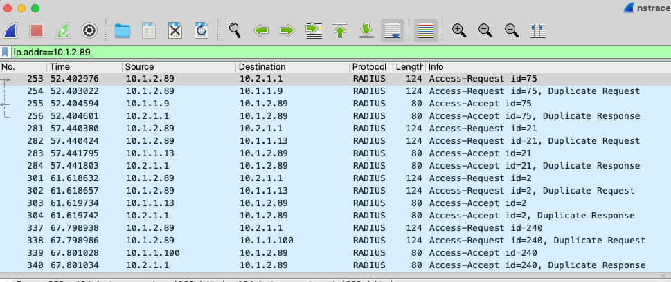
The capture contains packets from both internal and external interface and wireshark sees them as duplicates

Captures can also be saved in NSTRACE format which includes additional ADC specific information.


The following commands can be used to start trace from CLI. Once completed, the traces can be download via SCP from /var/nstrace.
> start nstrace -filter "CONNECTION.PORT.EQ(1812)" -size 1500 -traceformat PCAP -fileName radius
 Done
> show nstrace
        State:  RUNNING          Scope:  LOCAL            TraceLocation:  "/var/nstrace/16Nov2024_04_16_35/..." Nf:  24                  Time:  3600
        Size:  164               Mode:  TXB NEW_RX        Traceformat:  NSCAP      PerNIC:  DISABLED        FileName:  16Nov2024_04_16_35 Filter:  "CONNECTION.PORT.EQ(1812)"
        Link:  DISABLED          Merge:  ONSTOP           Doruntimecleanup:  ENABLED TraceBuffers:  5000      SkipRPC:  DISABLED       SkipLocalSSH:  DISABLED
        Capsslkeys:  DISABLED    Capdroppkt:  DISABLED    InMemoryTrace:  DISABLED
 Done
> stop nstrace
 Done
>
Unix Shell
To access Unix Shell, enter the following in CLI.
> shell
root@ns#
It is possible to run tcpdump from command line. Note that you must use this shell script and not tcpdump itself.
root@ns# nstcpdump.sh host 10.1.2.89
reading from file -, link-type EN10MB (Ethernet), snapshot length 65535
04:27:03.396185 IP 10.1.2.89.46398 > 10.2.1.1.1812: RADIUS, Access-Request (1), id: 0xb8 length: 82
04:27:03.396248 IP 10.1.2.89.46398 > 10.1.1.13.1812: RADIUS, Access-Request (1), id: 0xb8 length: 82
04:27:03.397179 IP 10.1.1.13.1812 > 10.1.2.89.46398: RADIUS, Access-Accept (2), id: 0xb8 length: 38
04:27:03.397185 IP 10.2.1.1.1812 > 10.1.2.89.46398: RADIUS, Access-Accept (2), id: 0xb8 length: 38